Precision finishing for aerospace & defense.

Over 35 years delivering precision where failure is not an option. We specialize in grinding, honing, lapping, and match fitting for mission-critical components. Our team uses specialized equipment and controlled processes to meet tight tolerances and demanding surface finish and fit requirements.

ORBIT MANUFACTURING · MID VALLEY GRINDING
01 Prototype through production02 Drawing-driven processes03 One manufacturing partner

Two divisions. One precision finishing partner.

ORBIT GROUP, INC. / DIVISION 01

Mid Valley Grinding

Mid Valley Grinding specializes in precision OD, centerless, and bar grinding for tight-tolerance components. We support aerospace, defense, medical, and commercial programs that require repeatable results and disciplined process control.

We focus on low- to medium-volume work where dimensional accuracy, surface finish, and on-time delivery matter to the next stage of production.

Speak with Mid Valley · (818) 764-1086 →
ORBIT GROUP, INC. / DIVISION 02

Orbit Manufacturing

Orbit Manufacturing provides precision ID honing, flat and ID lapping, match fitting, and functional testing. We work with OEMs and Tier 1 suppliers to meet demanding tolerance, geometry, and surface finish requirements.

Specialized equipment and our quality system support aerospace and defense work from first article through production.

Speak with Orbit · (818) 956-1383 →

Aerospace & defense.
Precision with a purpose.

Specialized manufacturing and finishing for demanding mechanical systems, with aerospace and defense at the center of our work.

01 / PRIMARY INDUSTRY

Aerospace

Precision features for commercial and defense aerospace applications.

  • Actuation components
  • Hydraulic and pneumatic parts
  • Precision shafts, sleeves, and spools
  • Close-fitting mating components
02 / PRIMARY INDUSTRY

Defense & Military

Controlled processes for programs where consistency and repeatability matter.

  • Servo valve components
  • Hydraulic control parts
  • Ground and airborne system components
  • Prototype through production
03 / ADDITIONAL INDUSTRIES

Industrial & Energy

Finishing for demanding pressure, wear, and control applications.

  • Industrial hydraulic components
  • Control system parts
  • Sealing and wear surfaces
04 / ADDITIONAL INDUSTRIES

Medical & Precision Equipment

Dimensional control and fine surface finishes for precision components.

  • Precision sleeves and shafts
  • Sealing surfaces
  • Close-tolerance cylindrical parts

Specialized processes.
Mission-critical details.

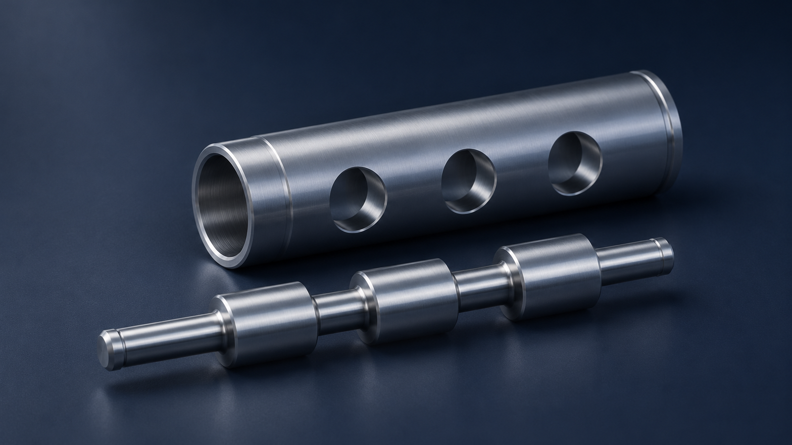
From precision bores to matched spool-and-sleeve assemblies, we review the features that matter to your component’s fit, finish, and function.

Illustrative component visualizations. Select a process for equipment imagery, technical characteristics, and quotation requirements.

From the drawing
to the finished feature.

Explore the process, the features it controls, and the information our team needs to review your part.

Illustrative precision finishing component
ILLUSTRATIVE COMPONENT / PROCESS FOCUS
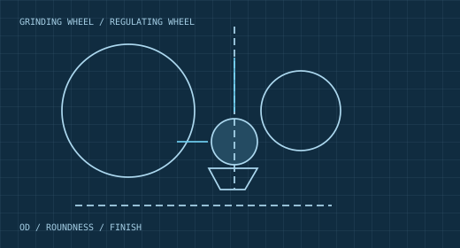
Illustrative centerless & od grinding process drawing
01 / External diameters / Mid Valley Grinding

Centerless grinding

Infeed handles shoulders, multiple diameters, and profiles by feeding the workpiece into the grinding zone. Thru-feed moves straight cylindrical parts continuously between the grinding and regulating wheels.

Infeed diameter
Up to 4″
Infeed grind length
Up to 12″
Diameter tolerance
To 0.0001″
Roundness
To 0.0001″
Surface finish
As fine as 4 Ra
Process selection
Infeed for profiles and interrupted lengths; thru-feed for continuous outside diameters.
Materials
Titanium, tungsten, molybdenum, nickel alloys, and other difficult materials, subject to review.
Technical review
Finished diameters, profile geometry, grind length, stock allowance, material condition, and finish.
Discuss this process →
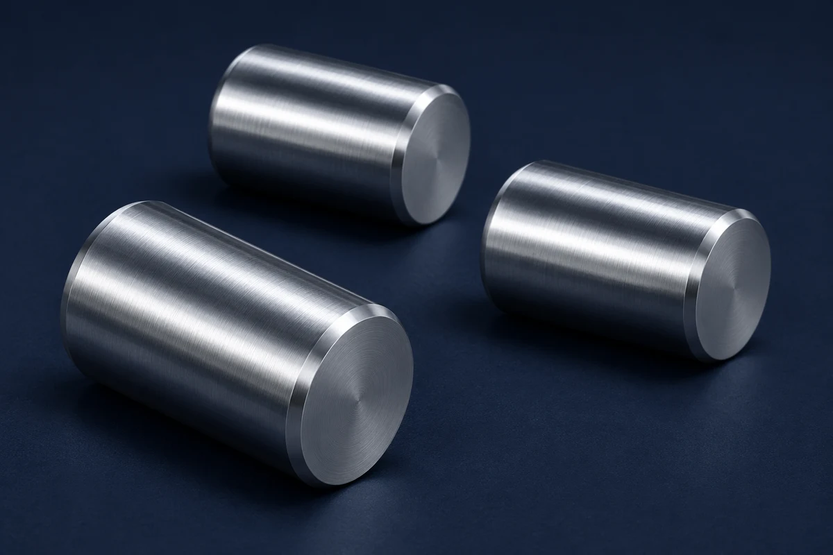
Three short steel rollers with straight, ground outside diameters and chamfered ends
ILLUSTRATIVE COMPONENT / PRECISION-GROUND STEEL ROLLERS
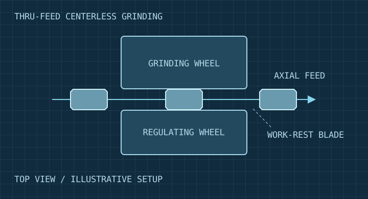
Top view showing short cylindrical rollers passing between the grinding and regulating wheels
02 / Continuous OD / Mid Valley Grinding

Thru-feed centerless grinding

A work-rest blade supports the part while a regulating wheel controls its rotation and feeds it lengthwise past the grinding wheel. Short rollers like those shown here have a straight, continuous outside diameter, allowing them to pass through the wheels in succession during repeat runs.

Typical parts
Straight pins, rollers, and cylindrical blanks
Geometry
Continuous OD with clearance to pass through the wheels
Drawing requirements
Finished OD, roundness, straightness, and surface finish
Setup review
Part length, material and hardness, and stock allowance

For a quote, share your drawing, starting and finished diameters, and lot quantity.

Request a thru-feed grinding quote →
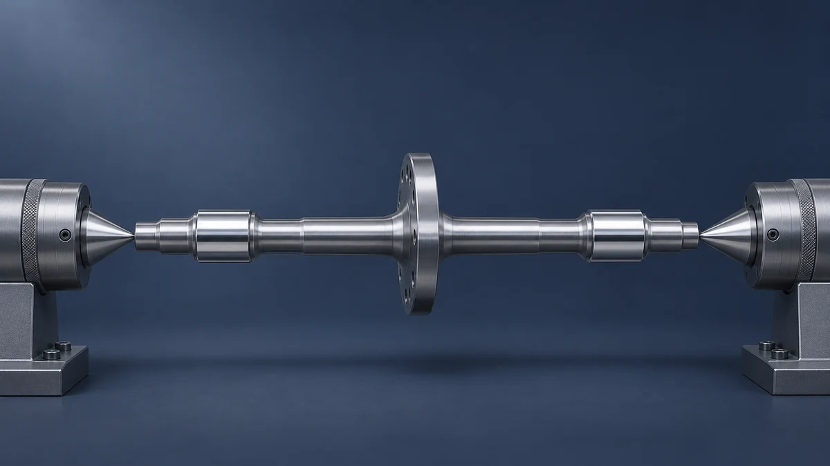
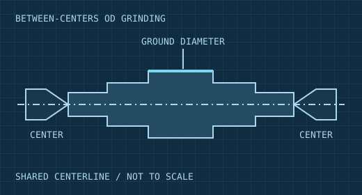
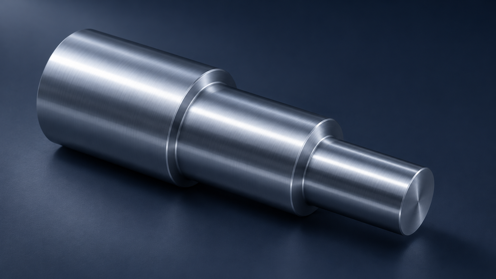
Illustrative ground spindle mounted between opposing centers
ILLUSTRATIVE SETUP / SPINDLE BETWEEN CENTERS
Between-centers setup showing the shaft centerline
03 / Datum-controlled OD / Mid Valley Grinding

Between-centers OD grinding

In between-centers grinding, centers support both ends of the part and establish its axis of rotation. This setup is useful when several diameters must run true to a common axis or meet a specified datum relationship.

Typical features
Shaft journals and stepped diameters
Drawing requirements
OD size, runout, and surface finish
Setup review
Center-hole condition and datum references

For a quote, share overall length, maximum OD, grind lengths, material and hardness, stock allowance, and the required tolerances.

Request a between-centers grinding quote →
Illustrative precision finishing component
ILLUSTRATIVE COMPONENT / PROCESS FOCUS
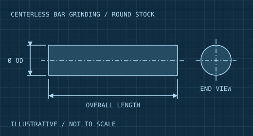
Illustrative bar grinding process drawing
04 / Long stock / Mid Valley Grinding

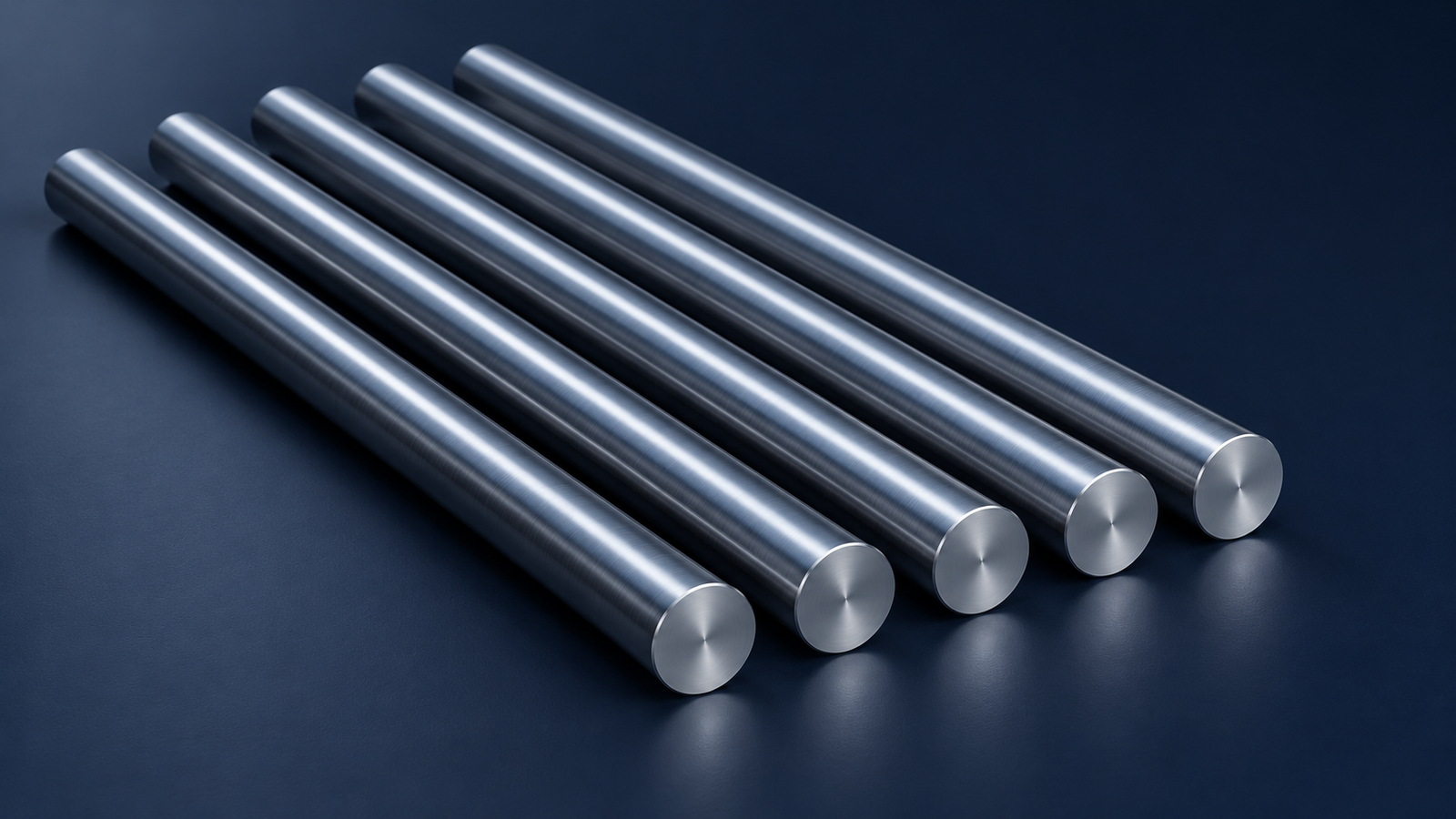
Bar grinding

Centerless bar grinding prepares long, semi-finished stock for subsequent manufacturing, focusing on outside diameter consistency, roundness, straightness, and surface finish.

Bar length
Up to 14′
12′ bar diameter
Up to 1.5″
Cut-length diameter
Up to 3″
Diameter tolerance
To 0.0001″
Roundness / finish
To 0.0001″ / 4 Ra
Materials
300/400-series stainless, alloy and carbon steels, aluminum, titanium, brass, medical grades, and exotics.
Typical work
Precision bar stock, shafts, and cylindrical blanks for downstream processing.
Technical review
Starting and finished diameter, bar length, quantity, straightness requirement, and material condition.
Discuss this process →
Illustrative precision finishing component
ILLUSTRATIVE COMPONENT / PROCESS FOCUS
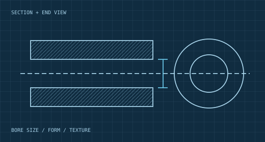
Illustrative precision id honing process drawing
05 / Bore geometry / Orbit Manufacturing

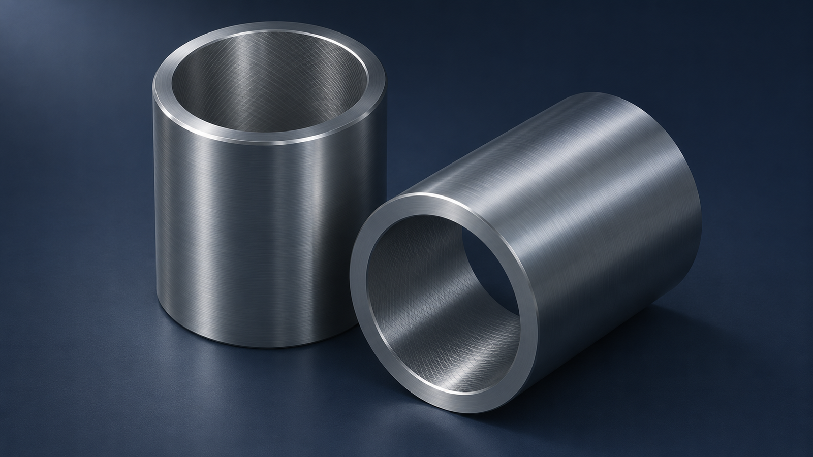
Precision ID honing

Precision ID honing refines internal bores where size, geometric form, and surface condition determine how a component seals, wears, and mates with another part.

Geometry
Size, roundness & cylindricity
Surface texture
Controlled crosshatch
Verification
Air gaging & in-process inspection
Process focus
Bore straightness, dimensional consistency, and surface finish tailored to the drawing.
Applications
Valve bodies, sleeves, hydraulic components, and other precision internal bores.
Technical review
Bore diameter and length, through or blind features, material, finish, and inspection requirements.
Discuss this process →
Illustrative precision finishing component
ILLUSTRATIVE COMPONENT / PROCESS FOCUS
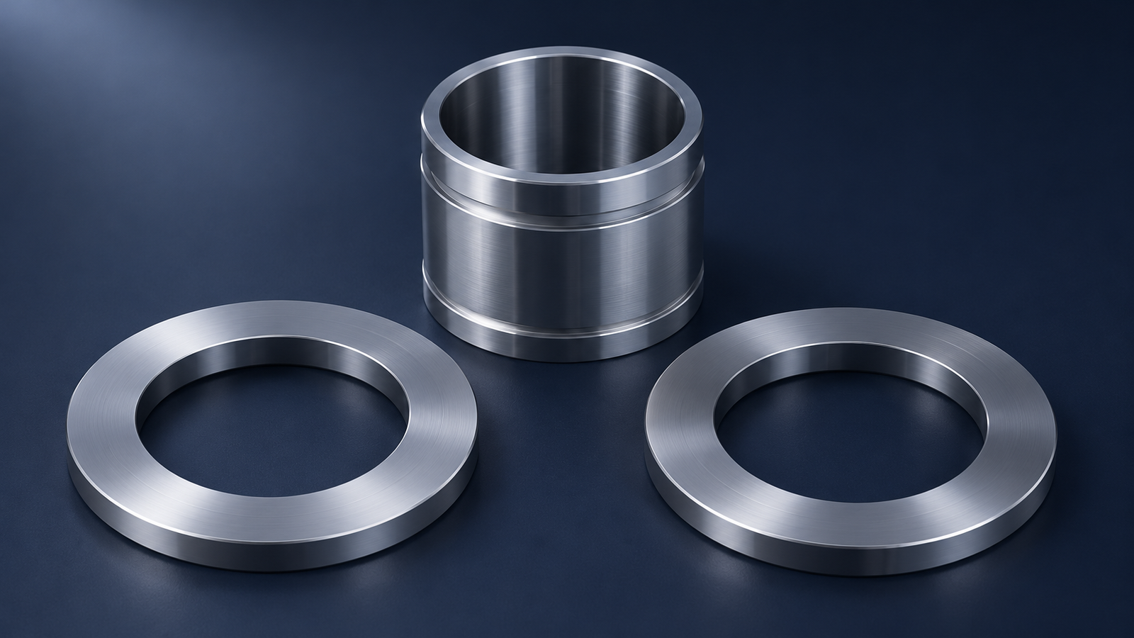
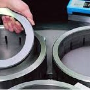
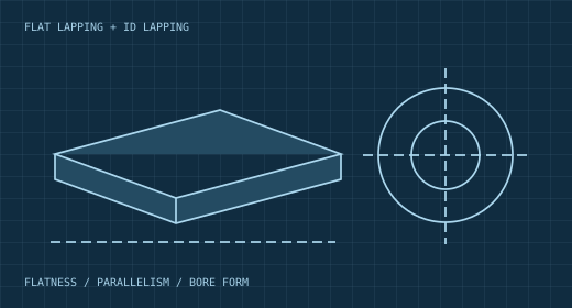
Flat lapping of precision ring faces
FLAT LAPPING / MATING SURFACES
Illustrative precision lapping process drawing
06 / Flat lapping + ID lapping / Orbit Manufacturing

Precision lapping

Precision lapping refines geometry and finish on surfaces where controlled contact, fit, and sealing matter. We select the approach around the feature, material, and functional requirement.

FLAT LAPPING

Mating faces · seal faces · parallel surfaces

ID LAPPING

Internal bores · sleeves · cylindrical fits

Flatness / parallelism
Down to 2 microinches*
Flat lapping
Faces & sealing surfaces
ID lapping
Internal cylindrical surfaces
Flat lapping
Control flatness, parallelism, size, and finish on mating faces, sealing surfaces, and precision flat components.
ID lapping
Refine bore size, straightness, roundness, and internal finish for sleeves and other close-fitting cylindrical components.
Additional geometries
OD cylindrical, counterbore, spherical, concave and convex features can be reviewed for application suitability.
Technical review
Contact geometry, flatness or bore form, finish, mating relationship, material, and acceptance method.
Discuss this process →
Illustrative precision finishing component
ILLUSTRATIVE COMPONENT / PROCESS FOCUS
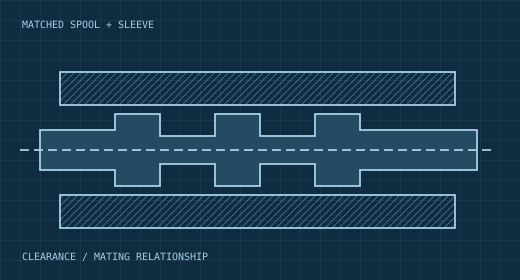
Illustrative match fitting process drawing
07 / Spools & sleeves / Orbit Manufacturing

Match fitting

Match fitting treats the spool and sleeve as a functional pair. Precision finishing establishes the specified relationship between their mating diameters, supported by verification appropriate to the assembly.

Published clearance
Down to 0.00002″*
Mating relationship
Spool OD / sleeve ID
Verification
Fit & functional requirements
Process focus
Clearance, size, roundness, straightness, and finish across the mating features.
Applications
Spool-and-sleeve assemblies, servo valve components, and precision hydraulic control parts.
Technical review
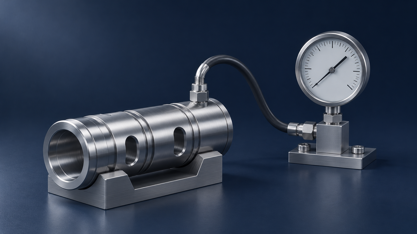
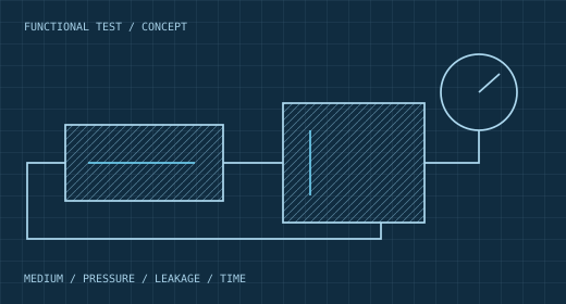
Paired component identification, clearance requirement, finish, leakage criteria, and test conditions.
Discuss this process →
Illustrative precision finishing component
ILLUSTRATIVE COMPONENT / PROCESS FOCUS
Illustrative leakage & vacuum testing process drawing
08 / Functional verification / Orbit Manufacturing

Leakage & vacuum testing

Dimensional inspection and functional testing answer different questions. Leakage and vacuum testing evaluate the performance of finished components and sealing surfaces under specified conditions.

Test media
Air & oil
Vacuum testing
Flat & precision sealing faces
Acceptance
Customer-specified criteria
Air & oil leakage
Evaluate spools, sleeves, and servo valve components at the required pressure, duration, and leakage limits.
Vacuum verification
Assess sealing integrity of flat and precision mating surfaces after finishing.
Technical review
Test medium, pressure or vacuum level, allowable leakage, test time, fixture needs, and reporting format.
Discuss this process →
Published capability figures are application-dependent and subject to drawing, material, geometry, and inspection review. *Minimum clearance and flatness figures are not blanket production guarantees. All technical sketches are illustrative and not to scale.

Explore component drawings

See how spools and sleeves fit together, how bore geometry is controlled, and how mating faces are finished.

ORBIT / ENGINEERING FOCUSFIG. 01 · SECTION VIEW

Illustrative drawings show process concepts only. They do not depict customer parts, production dimensions, or controlled technical data.

Your drawing is
the starting point.

We review drawing revisions, critical dimensions, material, surface finish, and functional requirements before recommending a finishing process. Quality and documentation requirements are confirmed during quotation.

Aerospace and defense are at the center of our work. From our Glendale, California facility, we support demanding manufacturing programs nationwide, alongside medical and commercial applications.

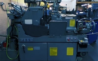
Centerless grinding equipment from Orbit’s existing website
SPECIALIZED EQUIPMENT. FOCUSED EXPERTISE.

Complementary grinding and precision finishing capabilities under Orbit Group.

AEROSPACEDEFENSEPRECISION HYDRAULICSFLUID CONTROL
01

Review the requirements

Share the process needed, part quantity, material, tolerances, surface finish, and requested delivery date.

02

Confirm the process

We review feasibility, inspection needs, and customer-specific requirements before confirming pricing and lead time.

03

Finish, inspect, and deliver

Our team processes and inspects to the agreed requirements, with documentation and packaging coordinated for your order.

Precision is measured.
Confidence is documented.

Orbit Group’s quality system supports aerospace, defense, and other mission-critical work where precision, traceability, and repeatability matter. We agree on acceptance criteria with your engineering and quality teams before production, then verify requirements during processing and at final inspection.

ITAR REGISTEREDAS9100 PRACTICESFAI SUPPORT
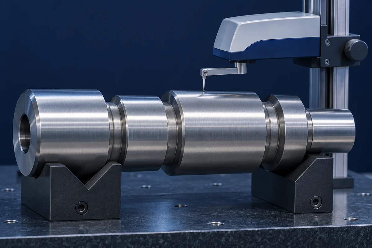
Illustration of a contact stylus checking the surface roughness of a stepped hydraulic spool
SURFACE FINISH VERIFICATION / ILLUSTRATIVE SETUP
BEFORE PRODUCTION

Requirements & traceability

  • Drawing and revision review
  • Customer-specific process requirements
  • Material traceability when required
DURING PROCESSING & AT FINAL INSPECTION

Inspection & measurement

  • Precision measurement and air gaging
  • In-process and final inspection
  • Surface finish verification
  • First Article Inspection support
FUNCTIONAL CHECKS & REPORTING

Testing & documentation

  • Air, oil leakage, and vacuum testing
  • Matched-component verification
  • Inspection reports per order requirements

Audits & quality reviews

We welcome customer and third-party audits. Your quality and engineering teams can work directly with ours to review process controls, inspection plans, and the documentation your program requires.

Request quality documentation →

Orbit Group

616 Irving Ave
Glendale, CA 91201

Monday–Friday, 7:00 AM–3:30 PM Pacific

Orbit Manufacturing
(818) 956-1383
Mid Valley Grinding
(818) 764-1086
Customer care
Customercare@orbitgrp.com
Get directions →

Request a quote

Share your finishing requirements and we’ll connect you with the right Orbit division.

For controlled drawings or technical data, contact our team to arrange an approved transfer method.

Prefer email? Contact Customer Care.